Welcome to our guide to Mechanical Ventilation with Heat Recovery (MVHR), highlighting details you won’t get from the manufacturer’s sales material. In our experience, they are important factors to consider before taking the plunge.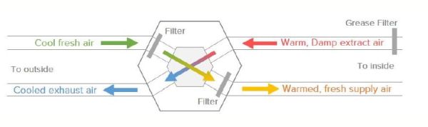
- Design (Sizing and Balancing). Ensure you employ someone to do a design prior to installation, if this is a manufacturer, be sure to vet their design.
- Check the MVHR unit selected is suitably sized for your property, if it is running at 80-90% of its capacity to service your property it may be undersized and create issues with noise post commissioning, if its running at 20-30% (or you have been quoted for two units) the system design may be oversized and you’ll be paying for too much equipment. Typically, if a unit is operating around 50-60% capacity and satisfies the properties (and Building Regulations) ventilation requirements then this is a good marker for correct unit sizing and efficiency and selection – most MVHR units available in the UK have been tested and rated for efficiency, and placed on a publicly accessible database. This makes it easy to compare machines on that criteria, but there are other factors to consider such as noise, size, electrical power* and controls features (see below). It is essential that the machine has a means to bypass the heat exchanger in the summer, when its desirable to have cooler fresh air to reduce the risk of overheating – and some sort of frost protection.
- Check the ductwork layout for clashes with architecture or structure – designs provided free by manufacturers are sometimes not well coordinated with the design. Secondly look at the ductwork lengths and sizes and ask for the pressure drop calculations. If your designer can’t provide these, they have not done a full design, and you should treat any information as only indicative or preliminary. Best practice is to design the system to be self-balancing, only requiring minor adjustments (designed for no more than +/- 10Pa at the air valve) with the air valves during set-up and commissioning. Domestic designs tend to avoid duct mounted volume control dampers because they are usually unnecessary and require access (e.g. via unsightly hatches). However, sometimes these are necessary to ensure the system can be properly commissioned, so thought must be given to good access.
- Unless there is a clear justification (via detailed acoustic calculation) to omit them, designs must include attenuators (silencers) on the supply and exhaust duct work. These should be at least 1m long, or of the elbow type; they should be concentric galvanized duct, not flexible foil. Lindab produce one semi-rigid type we have found to be satisfactory, but several flexible types that are not. If your ‘design’ does not include proper noise attenuation, it’s not a design!
- Location, location, location
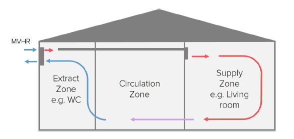
- Unless there is a very good reason not to, units should be located inside the thermal envelope (i.e. the insulation layer). It is essential the unit is located on or very close to an external wall, (or, less ideally roof/ceiling) to mimimise the internal ductwork distribution and the insulated intake and exhaust ductwork to outside. The air in those ducts is the same temperature as outside so the duct insulation has to do the same job as your wall insulation; unfortunately it’s impractical to insulate the ducts very thickly (50mm is good, 25mm is a bare minimum), so keeping the surface area of those ducts to the absolute minimum is the order of the day. Runs less than 1m each are best practice, anything over 3m should be re-designed.
- Access is important to make it easy to maintain (the key job is checking and changing the filters). We’d suggest checking the filters very regularly for the first year or so, until you get a feel for how frequently they should be changed. A variety of filter grades are available; most manufacturer provide G4 as standard, which will remove the bulk of dust in the outside air, but you may want to upgrade to an F7 which will take out finer particles including pollen. Some manufacturers are talking about more sophisticated filtration that can remove other pollutants. For this reason, as well as noise transmission, units should not be located in loft spaces.
- Locate the unit away from bedrooms and other sensitive areas to reduce the impact of breakout noise (i.e. noise coming out of the machine case) – if there’s no dedicated plant room, a utility room is a good choice.
- As well as primary attenuators selected and placed on the main MVHR supply and extract ducts to reduce noise travelling down the duct from the unit, consider cross-talk attenuation, in private areas or consider a manifold system with independent semi-rigid duct runs to each bedroom and WC.
- Controls (Manual or Automatic)
- Many controls features are ‘nice to have’ rather than ‘must have’ because a properly designed system should work fine if it spends its whole life running at the ‘standard’ flow rate, but some features are nice to have, such as automatic balancing (which makes it easier to commission), and filter alarms (timers or pressure sensors).
- Make sure you know what you want and check the unit can do it, this should include whether you want manual control of the unit, so you can turn it up and down as you see fit via fan speed control or whether you would like automatic control of the unit based on humidity or CO2. Do you want a remote control panel, an app based controller or are you happy to work with the control interface on the MVHR? All these decisions will add cost to your system, so don’t pay for what you don’t value.
- Air tightness (and SAP a strange quirk)
- If you’re designing a building that seeks to achieve an air permeability of greater than 3m3/m2h, a simpler continuous Mechanical Extract Ventilation (MEV) system may be just as appropriate from an energy standpoint, however there are additional benefits to having an MVHR system outlined in our downloadable guide, Greengauge’s Introduction to MVHR .
- In SAP if you changed the MVHR out for and MEV system the Dwelling Emission Rate (DER) would increase as expected but making the subsequent change to the air permeability (AP) target say from 5m3/m2h to 3m3/m2h, the DER remains the same but the Dwelling Fabric Energy Efficiency (DFEE) rate goes up. In fact, it only starts to change the carbon emissions (the DER) once the AP goes above 4m3/m2h.
- Commissioning
- It is essential that MVHR systems are properly commissioned in order to get the full benefits of energy savings, comfort and hygiene. The standard methods required in Part F leave some room for improvement, so ask in advance for some additional checks:
- The supply flow rates should be measured and adjusted, not just the extract rates.
- The total supply and total extract rates should be with 5% of each other (best practise) or 10% (good practise). If this is difficult, or requires a large difference in fan speeds, it’s likely the duct work design and/or installation is inadequate. The unit should be balanced at the normal/standard flow rate, not on boost or minimum rate.
- It is essential that MVHR systems are properly commissioned in order to get the full benefits of energy savings, comfort and hygiene. The standard methods required in Part F leave some room for improvement, so ask in advance for some additional checks:
*a properly designed, well-installed MVHR system in an airtight house will always save more energy in heat than it uses to turn the fans, by a significant margin.