Nowadays hydronic underfloor systems are something that are looked at for any project independently of its size, scope (residential, commercial, or even industrial) and type (new construction or renovation). A quick search on the internet could give you a good insight why this system could be preferable over a more traditional wet radiator system. The most important reasons for implementing these systems are:
- Rooms heated evenly (cold spots can be minimised, especially in refurbishments) with heating profiles (temperature perceived at different heights) close to the ideal one. A good example of this can be found in one of previous blog pieces (Project Focus – Warehouse UFH System)
- It is a more energy efficient system compared to traditional radiators not only for heating evenly the spaces and doing it in line with the ideal heating profile (more comfort for the occupiers with lower temperatures compared to radiators) but allowing the heating source to operate at lower temperatures (either it is a boiler, heat pump, etc.). Obviously, the total output required needs to be assessed carefully but generally hydronic underfloor heating systems will require 55°C (or lower) water coming out of the boiler or heat pump; radiators will require 75°C (the higher the temperature required at the heat source the lower the efficiency expected, this is especially applicable in heat pump systems), otherwise increasing their size will be required to compensate the important output drop.
- Underfloor hydronic system does not impact on aesthetics and gives more flexibility to the Architect, Interior Designer, etc.
- Keep the air in the space cleaner (radiators emit heat mainly by convection encouraging dust, etc. being suspended in air).
- It could be used for cooling as well (if it is connected to the right heating/cooling source and adequate gear is installed for monitoring its operation, etc.).
Outputs and BS EN 1264 role
In sight of all of these, it is indisputable that underfloor hydronic systems are great! And they are even greater when you quickly scan through some UFH manufacturer websites and discover outstanding outputs per square meter (W/m2)! Attending to those figures anybody could think that UFH is a suitable solution on its own for any scenario, however the importance of relevant factors could be overlooked.
To be fair, manufacturers usually indicate many parameters they used to calculate the output figures declared on their website, but sometimes important assumptions and considerations are omitted which could be misleading.
For a better understanding of the previous paragraph, we need to look to the design standard the calculated output figures are based on, this is “BS EN 1264 – Water based surface embedded heating and cooling systems”. This standard is dedicated mainly to the estimation (via calculation or testing) of heating/cooling outputs of hydronics systems integrated in different types of constructions (floors, walls, and ceilings). This blog piece will cover only the installation type A (underfloor system, most traditional and probably extended UFH type in construction) as classified on this standard and working as heat emitter.
The logic behind this document to estimate outputs can be summarised as follows:
- The output expected from our installation will be related to many different factors such as:
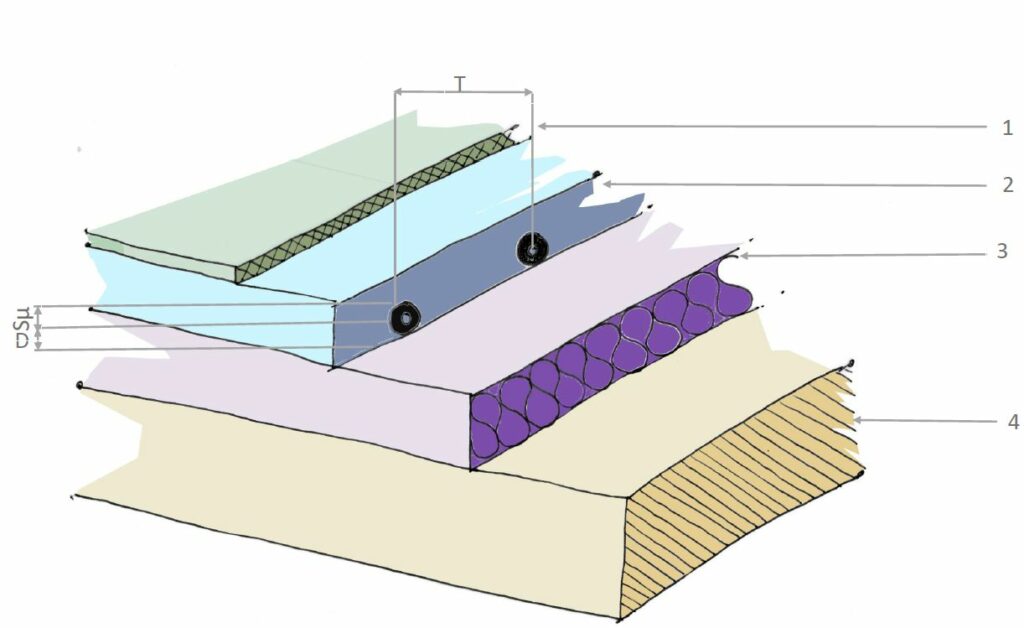
- Installation pipe pitch (T).
- Screed thermal conductivity (ʎE) and screed thickness above the pipe (SU).
- UFH Loop pipe size (da), wall thickness (SR) and thermal conductivity (ʎR).
- Design room temperature (ϑi).
- Type of floor finish and its thermal resistance (Rλ,B).
- Water temperature drop (σ).
BS EN 1264 gives the required tools to relate all those factors and unwrap the equation to estimate the heat output (q). This equation is unique to each type of construction (each geometry/materials-properties/conditions combination delivers different results), and it is what is called “Characteristic curve” of the installation.
- The equation above will throw results of different outputs in relation to flow/return water temperatures although it does not consider floor surface comfort temperatures. To sort this out BS EN 1264 introduced a different curve – the “Limit curve” – that define the max. output per square meter that is possible achieving (qg) in such way comfort surface temperatures are not exceeded (qg > q condition must be fulfilled always). Max. comfort temperatures are summarised below:
- 29ºC in living spaces, bedroom, etc. 33ºC in bathrooms 35ºC in perimeter of rooms
Each characteristic curve is associated with a unique limit curve which is a function of the following values:
- Installation pipe pitch (T).
- Screed thermal conductivity (ʎE) and screed thickness above the pipe (SU).
- Design room temperature (ϑi).
- And max. surface temperature (ϑF,max).
To illustrate these concepts, we can use Figure 2 where curves were plotted for a system with following parameters:
- Pipe pitch | T: 150mm
- Max comfort surface temperature | ϑF,max: 29C
- Room temperature | ϑi : 20C
- PEX Pipes | da: 16mm | wall thickness – SR: 2mm | thermal conductivity – ʎR: 0.35W/mK
- Standard sand/cement screed | thickness above pipes – SU: 65mm | thermal conductivity – ʎE: 1.2W/mK
- Floor finish | Floor finish resistivity – Rλ,B: 0.01m2K/W
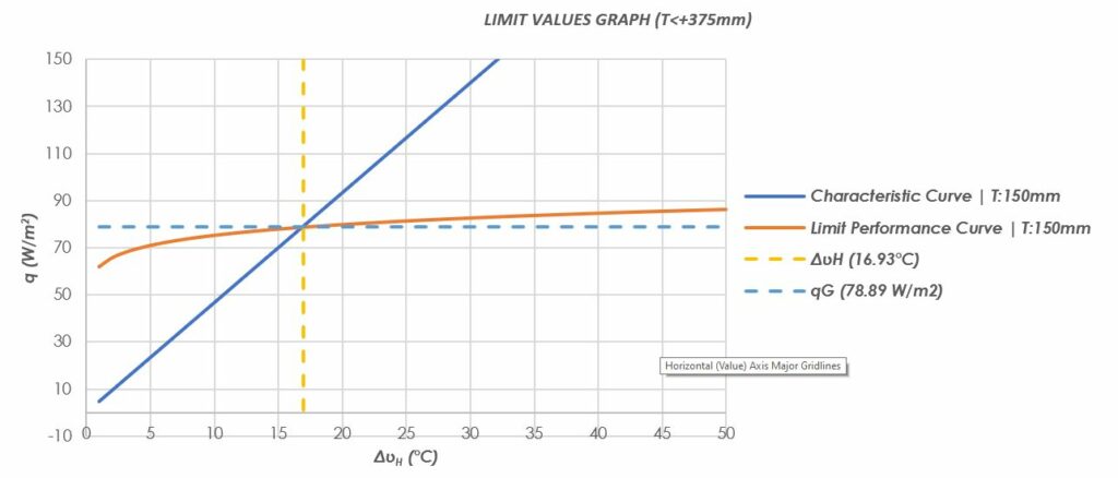
(*) ΔυH – LMT – Logarithmic mean temperature difference between carrying fluid and room temperature
From Figure 2 it can be inferred that we will not be able extract more than ~78W/m2, the figure that is represented at the intersection point between the characteristic and limit curves.
So, what is the problem then?
One problem is the manufacturers not indicating clearly what max. surface temperature they have assumed for their calculations in addition to the design team’s (if there is one…) vague knowledge of this standard could be problematic.
This is especially important in renovations. It is not uncommon for us to talk to clients who have expectations of omitting radiators (and having a brand new highly efficient heat pump to deliver the heat demand) on their refurbished property as declared UFH output figures on some websites are remarkably high. If these beliefs are not stopped quick enough it could lead to unpleasant adjustments (once the occupier understand enough heat is not delivered) with subsequent impact on overall efficiency of the system and comfort levels (additional emitters could be even required if the shortfall output is too great).
And how to ensure our system will perform as expected?
The following “recipe” will cover the most important areas and guarantee everything will work as it should do:
- Investing in fabric and air tightness is a key point, this will ensure heat losses will be low enough making the UFH a suitable solution every time. Also lowering the heat losses will mean that the radiator’s size could be kept to the minimum making of them a viable option with potential savings if the budget is tight for UFH.
- Understand your floor build-ups. Manufacturers usually give output values for standard UFH constructions (completely reasonable as explained before every type of construction has its unique “characteristic” and “limit” curve). Knowing the type of concrete and its thickness above the pipes as well as the floor finishes for different rooms is important (some of these parameters could halve the heating output!), as well as understanding the suitability of the floor finish (special attention to carpeted floors, limit its TOG value as much as possible) to work in conjunction to UFH (max. surface temperature, etc.). Type of pipe used (diameter, wall thickness) influence on the output is much lower compared to parameters mentioned previously (this does not imply that all UFH pipes are the same, manufacturer warranties, quality, lifespan, etc. could be quite different from one supplier to another).
- Ask your engineer/installer for a heat loss analysis on room-by-room basis (using for example BS EN 12831) and cross check these figures against UFH outputs calculated using the relevant standard.
Written by Oscar Garcia-Mendez